Place dry coolers efficiently and prevent hot air recirculation
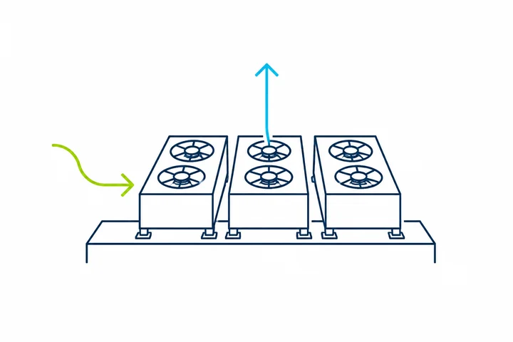
Cool intake air determines capacity and efficiency
Dry coolers reject large heat loads to the outdoor air. If warm exhaust air is drawn back into the units, entering air temperature and fan power rise while cooling capacity and efficiency fall. Flow simulation allows us to verify the arrangement during design and compare reliable improvements.
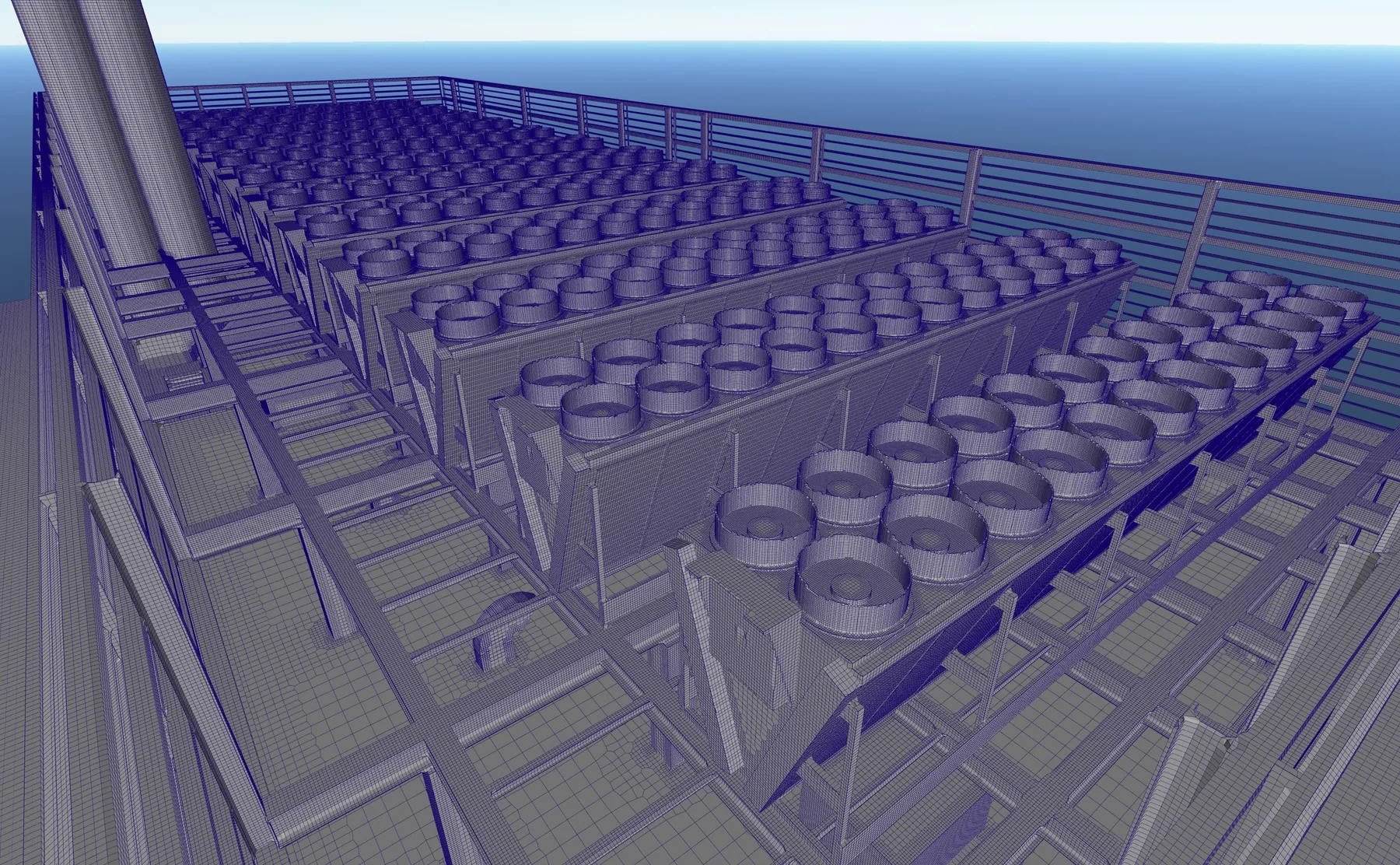
Every dry cooler is meshed in detail
Dry coolers, fans, intake surfaces, enclosures, railings, parapets, rooftop equipment and neighbouring buildings are represented geometrically. The computational mesh is strongly refined around the units and air paths. This reveals local recirculation and different intake conditions for individual units.
- Local refinement at fans and heat exchangers
- Representation of parapets, louvres and rooftop equipment
- Individual assessment of each dry cooler
- Adequate resolution of warm exhaust plumes
Warm exhaust air must not return to the intake
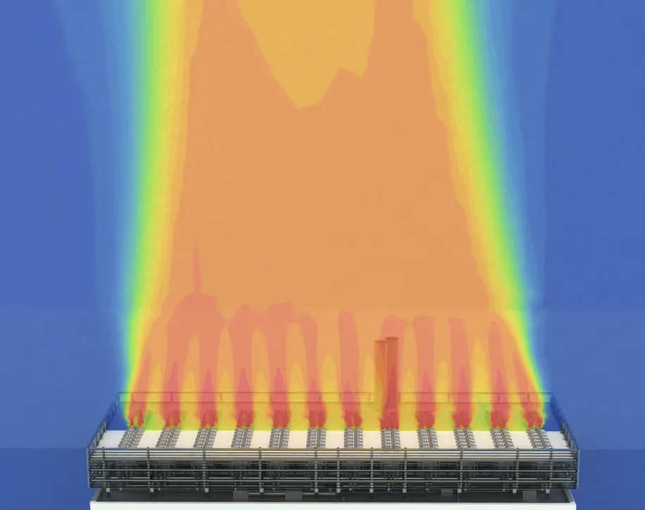
Hot air recirculation occurs when wind, screens or an unfavourable arrangement return heated exhaust air to an intake zone. The simulation visualises this flow path and quantifies the resulting entering air temperatures.
From weather data and load case to an optimised arrangement
Representative summer conditions, critical wind directions and suitable operating states are investigated. Full load, part load, staged fan operation and the outage of individual units can be considered.
- 01
Capture the geometry of the building, rooftop equipment and dry coolers
- 02
Define outdoor temperature, wind direction, wind speed and heat load
- 03
Model fan airflows and discharge temperatures
- 04
Evaluate intake temperatures, recirculation and airflow distribution
- 05
Compare spacing, height, orientation, screens and operating strategies
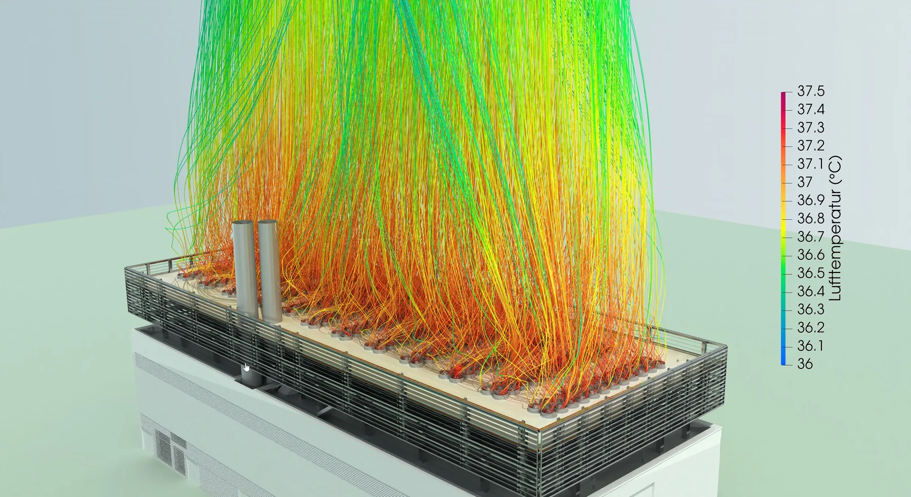
Assess temperature and airflow path together
Temperature coloured streamlines show how warm exhaust air leaves the plant roof and whether it is drawn into other units. Interactions, wind dependent weaknesses and the effect of an optimisation option become immediately visible.
Compare placement, capacity and energy demand reliably
The assessment connects local flow conditions with dry cooler performance data. It identifies the arrangement that supplies sufficiently cool intake air and operates efficiently under critical boundary conditions.
Frequently asked questions
When is a dry cooler simulation useful?
For multiple units, confined plant roofs, high heat loads, screens, neighbouring buildings or whenever the available cooling capacity must be demonstrated reliably.
Which weather cases are investigated?
Typical cases combine critical summer air temperatures with several relevant wind directions and speeds. Selection is matched to the site and operating requirements.
Can efficiency be assessed?
Yes. Simulated entering air temperatures and airflows are linked with unit performance data to assess capacity losses and additional energy demand.
Which variants can be compared?
Spacing, unit height, orientation, screens, louvres, discharge direction and different fan operating states can all be compared.
Verify dry cooler performance early in design
We define the arrangement, operating cases, weather conditions and required outputs with you.